http://process-eng.blogspot.com/?m=1
Sunday, May 21, 2023
Saturday, January 7, 2023
Control valve sizing
https://whatispiping.com/control-valve-sizing/
https://blog.fluidflowinfo.com/control-valve-sizing
Sunday, February 21, 2021
SWS
https://www.google.com/url?sa=t&source=web&rct=j&url=https://img1.wsimg.com/blobby/go/0337b61a-d8fc-4d81-a558-c88677c1492c/downloads/Engel%2520-%2520Seven%2520Deadly%2520Sins%2520of%2520Sour%2520Water%2520Stripp.pdf%3Fver%3D1570137227228&ved=2ahUKEwiJyvfEmfHuAhUhheYKHSDCBrg4ChAWMAl6BAgCEAE&usg=AOvVaw2s1DGb8bOCjcYTjx1W94iB
Crude Oil to chemicals
Exxon


https://gpcaforum.net/wp-content/uploads/2019/12/FINAL__MASTERCLASS-3__COTC.pdf
https://www.futurebridge.com/blog/crude-oil-to-chemicals-future-of-refinery/#:~:text=Hengli's%20Refinery%2DParaxylene%20Complex%3A%20The,bbl%20crude%20oil%20per%20year.
HAZOP
https://www.google.com/url?sa=t&source=web&rct=j&url=https://cbe.ust.hk/safetycourse/download/09.1HAZOPStudyTrainingCourse.pdf&ved=2ahUKEwij_KOUuvvuAhXRpOkKHfPcAqU4KBAWMAV6BAgDEAI&usg=AOvVaw2eOd1lHTPMGTgsVIUp5pI-
Cooling tower
https://www.slideshare.net/mobile/ctlin5/cooling-towers-10684323
https://missrifka.com/utility-system/cooling-tower-makeup-water.html
Refinery Overview
- https://www.e-education.psu.edu/fsc432/node/3
Flowserve refinery flowsheet
- Refinery gas - Made up of methane and ethane. This stream remains a gas and is sent to the fuel system
- Propane - Blended into LPG or used for refinery fuel
- Butane - Blended into LPG or used as refinery fuel
- Light straight run naphtha - Sold as a petrochemical feedstock, blended into gasoline, or upgraded through isomerization
- Heavy naphtha - Mostly upgraded through the reformer
- Kerosene - Used to make jet fuel or blended into diesel
- Atmospheric gasoil - Used to make diesel or converted to gasoline through the FCC
- Atmospheric bottoms - Contains all of the hydrocarbons that do not vaporize. It is typically fed to the vacuum distillation unit for further separation
- VGO or Vacuum gasoil - Typically sent to the FCC or hydrocracker to be upgraded into light products
- Vacuum resid - Literally the bottom of the barrel. Typically blended into residual fuel oil or upgraded through a coker or visbreaker
| Butanes and Lighter | |
| Light SR Naphtha | 90 - 190o F (32-88o C) |
| Heavy Naphtha | 190 - 380o F (88 - 193o C) |
| Kerosene | 380 - 520o F (193 - 271o C) |
| Light Gas Oil | 520 - 610o F (271 - 321o C) |
| Heavy Gas Oil | 610 - 800o F (321 - 425o C) |
| Light Vacuum Gas Oil | 800 - 950o F (425 - 510o C) |
| Heavy Vacuum Gas Oil | 950 - 1050o F (510 - 564o C) |
| Vacuum Residue | > 1050o F (>565o C) |
Saturday, February 20, 2021
Challenges Value Addition
1. Naphtha splitter change in design basis.
Initially 2 specs
ASTM D86 gap
RVP of light naphtha
2. Determine vessel thickness, weight so that temp drop is limited to match metallurgy temperature limit
3. Revamp - Column design pressure 3.5 kg/cm2g and FV. FV governing vessel wall thickness. increased design pressure to reduce relief load to existing flare
4. SWS - Suggested Pump around configuration
5. BPCL - hourly v/s daily labor rate in the proposal
6. Coal gasification - licensor selection - coal washing - water pollution
7. Fertilizer - Single large train for the given capacity
8. PSV - mechanical stop in CV
9. Combining NRU and thermal oxidizer
10. Reliance - Existing char filter was not functioning properly. Addition of cyclone with 10" W.C. pressure drop.
11. AUTO RECIRCULATION VALVE
12. Training program
13. Right at first pass. Take 10-20% additional time but reduce changes and corrections at later stage. When audit happened, project achieved better results than benchmark and other projects.
14. Mechanical stop on control valve to check relief load.
15. Asked to stop at acetic acid while project was to make Ethanol for fuel blending for better economics. Sale part acetic acid and use remaining for Ethanol production
15. Iocl DFR cw and power study
16. Add VFD on pump drive
https://www.linkedin.com/pulse/benefits-using-variable-speed-drives-pumps-all-engineers-kevin-brown
https://joliettech.com/blog/flow-control-valves-versus-variable-speed-drives-which-you-should-choose-and-why/
http://www.vfds.org/vfd-versus-control-valve-for-pump-flow-controls-580010.html#:~:text=A%20pump%2Fcontrol-valve%20combination,the%20pump%20or%20the%20VFD.
Naphtha hydrotreating
| Technology to Improve HSD Quality[1-2,17-19] | |||
| DHDS(35+bar pressure) | When one sulfur reduction is required | ||
| DHDT(85+bar pressure) | Large sulfur reduction & high cetane gain coupled with T-95 point improvement | ||
| Hydrocracker | For middle distillate maximisation along with cetane improvement & very high sulfur reduction | ||
- Hydrotreating[1-2]
- Remove hetero atoms and saturate carbon-carbon bonds Sulfur, nitrogen, oxygen, and metals removedOlefinic & aromatic bonds saturated
- Reduce average molecular weight & produce higher yields of fuel products
- Minimal cracking
- Minimal conversion – 10% to 20% typical
- Products suitable for further processing or final blending
- Reforming, catalytic cracking, hydrocracking
- Hydrocracking
- Severe form of hydroprocessing
- Break carbon-carbon bonds
- Drastic reduction of molecular weight
- 50%+ conversion
- Products more appropriate for diesel than gasoline
| Hydroprocessing Catalysts |
|
| General Effects of Process Variables[1-2,12-16] |
|
|
- Liquid hourly space velocity ~ 2
- Hydrogen Recycle about 2000 scf/bbl
- Stripper overhead vapour to saturate gas plant
- Recovery of light hydrocarbons and remove H2S
- Fractionator Pentane/hexane overhead to isomerization
- Bottom to reformer
| Hydrotreating[1-2,30-35] |
|
| Naphtha Hydrotreating-Hydrogen Consumption[1-2,30-35] |
|
This is chemical hydrogen consumption
 |
| Naphtha Hydrotreating - Process[1-2,30-35] |
|
| Distillate Hydrotreating |
|
| Distillate Hydrotreating-Hydrogen Consumption[1-2,30-35] |
|
| Heavy distillate (diesel) hydrotreating consumption quite variable |
|
| Typical conditions – 300oC – 425oC ; 300 psig and greater Modest temperature rise since reactions are exothermic |
|
 |
Fig:6.17 Typical Distillate Hydrotreater for Base Metal Catalyst |
https://www.slideshare.net/hels92/chapter-6a-hydrotreating
https://www.google.com/url?sa=t&source=web&rct=j&url=http://www.echemcom.com/article_96609_8b2fc5fee56526741cf17e7b663065df.pdf&ved=2ahUKEwia8Iaw8vPuAhU-8HMBHZ7pBHA4ChAWMAR6BAgEEAI&usg=AOvVaw19Dxh3fhgKAGN0kopOqpUl
https://nptel.ac.in/courses/103/102/103102022/
Thursday, February 18, 2021
Plot plan guidelines
https://thepipingtalk.com/rules-for-development-of-plot-plan/#:~:text=Flare%20location%3A,open%20flames%20by%20prevailing%20wind.
Process flow sequence and operating procedures should be thoroughly understood so that equipment arrangement in the plot plan is functional. Equipment should be arranged in logistic process sequence for optimum piping runs and operational and maintenance ease. Spacing between equipment shall be adequate for undertaking maintenance jobs.
(b) The unit pipe rack should be kept in the centre, thereby splitting the unit into two or more areas of equipment. Pumps may be arranged in two rows close to and on either side of the pipe rack.
Heat Exchangers and vessels should be grouped together forming outer rows on both sides of the rack.
(c) Heat exchangers should be located perpendicular to the pipe rack on the outer row to facilitate pulling of tube bundles with mobile crane or by other means. Shell and tube heat exchanger
should have a longitudinal clearance of at least one-meter plus the length of removable bundles.
(d) Air fin coolers should be installed above the pipe rack / technological structures / independent structure. Pumps handling hydrocarbons above the temperature of 230C or C4 and Lighters
should not be installed underneath the air fin coolers.
(e) Vessels having large liquid hold-up should be installed at lower heights and preferably at grade. Adequate drainage should be provided around such vessels. Where process requirement dictates
their installation above grade, these should be located in open area.
(f) Towers / columns should be located along the pipe rack towards open areas for unobstructed erection as well as maintenance of internals at grade. Tall towers requiring frequent operating
attention at upper levels may be located at one place so that common connecting platform can be provided.
(g) Thermo-siphon reboilers should preferably be placed close to their associated towers.
(h) Vessels, column, Reactors with internals and / or containing catalysts, chemicals etc should have a drop-out area for removing / installing the internals and / or for loading / unloading of catalysts and chemicals.
(i) Heaters should be located up wind at one corner of the unit. Space should be provided for removal and cleaning of heater tubes besides approach for crane. Areas around the heaters shall be graded for guiding spills away from process equipment. Forced Draft fans shall be located away from process equipment from where they are likely to suck hydrocarbon vapors.
J) No trenches or pits which might hold flammables should extend under the furnace and connections with underground drain system should be sealed over an area 15 meters from the
furnace walls.
(k) The local control panel for soot blower control and flue gas analyzer only should be located on and near the process heater. The rest of controls should be taken to control room.
(l) Gas compressors should be located down wind from heaters so that leaked gases will not drift towards the heater. Gas compressors should have roofing and open from sides to avoid accumulation of heavier vapours/gases on the floor of compressor house. Compressor house should be located near the battery limits to facilitate ease in maintenance and operation. Drop
out area should be provided for maintenance.
(m) No other tankage except day tanks / process chemicals shall be provided within battery limits of any process unit.
(n) Process chemicals storage tanks should be provided with kerb wall of minimum 300-mm height. Hydrocarbons day tanks shall be provided with dyke in line section 7.0 of this standard.
(o) Cold boxes should be located on grade or on separate elevated structures. Adequate space should be provided around cold boxes for ease of operation and maintenance.
(p) Flare knock out drum for the process units should be located at battery limit of the unit.
(q) Blow down facilities / buried drum should be located at one corner of the plant farthest from furnace or any fired equipment and on the lee-ward side of the unit. Vent from Blow down facility shall be minimum 6m above the highest equipment falling with in radius of 15 m from the vent stack.
(r) Operators cabin may be provided in the process unit. The cabin should be located upwind side of the unit in non-hazardous area and away from draining / sampling facilities. The cabin should be for minimum occupancy of the shift operators of the respective facilities only.
(s) Stairways should be provided for the main access.
(t) Minimum headroom under vessels, pipes, cable racks, etc should be 2.1 meters.
(u) Equipment should be spaced to permit use of mobile equipment and power tools or servicing and maintaining equipment during turn around periods.
Friday, February 12, 2021
Vacuum Tower
https://blog.wika.us/knowhow/improving-vacuum-tower-yield-product-quality-advanced-temperature-measurement/
Increase throughput
https://www.digitalrefining.com/article/1000973/a-balanced-approach-to-vacuum-tower-flash-zone-wash-section-design#.YCWCDOgzbIU
https://cdn.digitalrefining.com/data/articles/file/581376146.pdf
https://www.digitalrefining.com/article/1000291/vacuum-pressure-control-impact-on-profitability#.YCWFC-gzbIU
Transfer Line Hydraulics
https://cdn.digitalrefining.com/data/articles/file/293360342.pdf


Tuesday, October 6, 2020
Pump Sizing
Centrifugal Pumps: Flowrate inversely proportional to outlet pressure
Positive Displacement Pumps: Flowrate largely independent of the pressure
Pump Sizing:
Matching pump pressure and flowrate with system required flowrate and pressure. Pumps needs generate pressure high enough to overcome hydraulic resistance of the pipes, fittings, CV.
System Head: Static Head + Frictional Losses + Fitting Losses
- Amount of pressure required to achieve given flowrate in the system downstream of the pump.
- System head is not the fixed value. Higher the flowrate, higher the system head
- System Curve: Relationship between flowrate and hydraulic resistance of the system
- System head consists of
- Static head: Fixed value. Due to elevation difference between pump centerline and discharge
- Dynamic head: Varies dynamically with flowrate. Losses of energy due to friction in piping, fittings, change in fluid flow direction, opening of valves etc. It consists of Frictional losses + Fitting losses.
Dynamics losses ∝ Fluid Velocity
dP ∝ Q^2
Pump Curve:


Pump Hydraulic Power:
Power = Q.(ρ.g.h) = Q.dP
Power (W), Q(m3/s), others in SI unit
Pump Affinity Laws:
Law 1. With impeller diameter (D) held constant:
Law 1a. Flow is proportional to shaft speed:[1]

Law 1b. Pressure or Head is proportional to the square of shaft speed:

Law 1c. Power is proportional to the cube of shaft speed:

With shaft speed (N) held constant and for small variations in impeller diameter via trimming:
The volumetric flow rate varies directly with the trimmed impeller diameter:[3]

The pump developed head (the total dynamic head) varies to the square of the trimmed impeller diameter:[3]

The power varies to the cube of the trimmed impeller diameter:[3]

- These laws assume that the pump/fan efficiency remains constant i.e. , which is rarely exactly true, but can be a good approximation.

- NPSH

NPSHr:
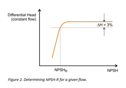
Manufacturers test pumps under conditions of constant flow and observe the discharge pressure (differential head) as NPSH (the suction pressure) is gradually reduced. Tests are usually performed with water at 20°C. NPSH-R is defined as the value at which the discharge pressure is reduced by 3% because of the onset of cavitation (Figure 2). NPSH-R is sometimes shown as NPSH3 or NPSH3% to highlight this fact. For multistage pumps, only the first stage is taken into consideration for determining the 3% pressure drop.
NPSH margin is typically 10% or 1 meter.
Sunday, October 4, 2020
Tanks
Fixed roof:
Floating roof:
- vapor pressure < 1.5 psia
- atmospheric and vacuum gas oils, vacuum residue
Floating roof:
- vapor pressure upto 11 psia
- Crude oil, naphtha, kerosene
API 650
- Atmospheric tank
- API 650 tanks can be designed upto 2.5 psig per Appendix F of this standard.
- Vacuum: 1 inch of water
- Design temperature: Limited to a maximum temperature of 200 deg F. 500 deg F, provided additional requirements of Appendix M are met
API 620
- API 620 tanks can be designed upto 15 psig
- Vacuum: 2-2.5 inch of water
- Design temperature: 250 deg F max
- e.g. light naphtha
VOLUME OF STORED LIQUID
- Tank type typically decided by liquid properties
- Fixed roof tanks are usually the least expensive, followed by floating roof tanks and dome roof tanks, in that order
- For very large sizes, construction of fixed roof tanks becomes more involved with very high cost for supporting the roof
- No limit on diameter by code or universal convention
- Typically fixed roof tank diameter upto 50 m - 65 m
FACTORS LIMITING SIZE OF INDIVIDUAL TANKS
- Local codes that put a cap on maximum volume within a single dyke.
- Soil bearing strength and piling requirements that could cap the maximum height.
- Plot shape and dimensions that could limit maximum diameter.
- Plot elevation profile - slopes could limit maximum diameter.
- Material constraints - maximum available tank plate thickness.
- Construction constraints
Example:
Normal liquid temperature = 40C
Assume temperature rise due to thermal radiation = 10C
Maximum liquid temperature = 40C + 10C = 50C
Vapor pressure of stored liquid @ 50C = 1.28 kg/cm2
Set pressure of Inbreathing Vent = 1.28 kg/cm2
Set pressure of Outbreathing Vent = 1.28 + 0.05 = 1.33 kg/cm2a
Set pressure of emergency vent = 1.33 + 0.05 = 1.38 kg/cm2a
Design pressure = 1.38 kg/cm2a
Design Vacuum = 2.5 " wc
Design Temperature = Larger of [Op Temp + 20C] or 65C = 65C
Vessel Sizing
Vertical v/s Horizontal
Vertical: Minimization of layout area, greater selectivity in level control, high volume fraction of gas, small volume vessel
Horizontal: Low volume fraction of gas, long residence time for liquid, rapid variation in flowrate
Steps: 1. Calculate vessel diameter to satisfy separation and L/D, 2. Calculate T/T for surge/hold up
Target particle separation: Particle diameter is known. Typically know for typical services
Vertical vessel:
Determine vessel cross sectional area such that-
Allowable vertical velocity of vapor phase = Settling velocity of liquid particle * Margin
Margin: 0 to 1


Horizontal Vessel


Subscribe to:
Comments (Atom)
-
 Fraction of the crosssectional area available for vapourliquid disengagement decreases when the downcomer area is increased. Thus, optimum d...
 -
1. Naphtha splitter change in design basis. Initially 2 specs ASTM D86 gap RVP of light naphtha 2. Determine vessel thickness, weight so th...
