Tuesday, October 6, 2020

Pump Sizing

Centrifugal Pumps: Flowrate inversely proportional to outlet pressure

Positive Displacement Pumps: Flowrate largely independent of the pressure

Pump Sizing: 
Matching pump pressure and flowrate with system required flowrate and pressure. Pumps needs generate pressure high enough to overcome hydraulic resistance of the pipes, fittings, CV. 

System Head: Static Head + Frictional Losses + Fitting Losses
  • Amount of pressure required to achieve given flowrate in the system downstream of the pump.
  • System head is not the fixed value. Higher the flowrate, higher the system head
  • System Curve: Relationship between flowrate and hydraulic resistance of the system
  • System head consists of 
    • Static head: Fixed value. Due to elevation difference between pump centerline and discharge
    • Dynamic head: Varies dynamically with flowrate. Losses of energy due to friction in piping, fittings, change in fluid flow direction, opening of valves etc. It consists of Frictional losses + Fitting losses.
                                                 Dynamics losses  Fluid Velocity

                                                                dP ∝ Q^2

Pump Curve:


Pump Hydraulic Power:

Power = Q.(ρ.g.h) = Q.dP
Power (W), Q(m3/s), others in SI unit


Pump Affinity Laws:

Law 1. With impeller diameter (D) held constant:

Law 1a. Flow is proportional to shaft speed:[1]

Law 1b. Pressure or Head is proportional to the square of shaft speed:

Law 1c. Power is proportional to the cube of shaft speed:


With shaft speed (N) held constant and for small variations in impeller diameter via trimming:

The volumetric flow rate varies directly with the trimmed impeller diameter:[3]

The pump developed head (the total dynamic head) varies to the square of the trimmed impeller diameter:[3]

The power varies to the cube of the trimmed impeller diameter:[3]


These laws assume that the pump/fan efficiency remains constant i.e. , which is rarely exactly true, but can be a good approximation.

NPSH


NPSHr: 
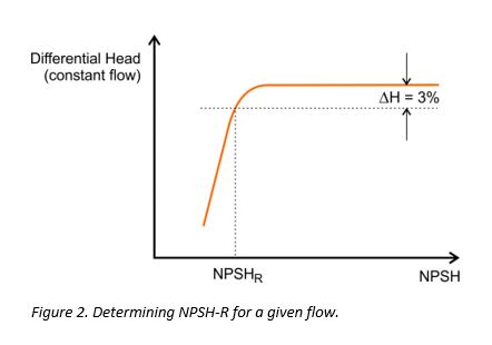
Manufacturers test pumps under conditions of constant flow and observe the discharge pressure (differential head) as NPSH (the suction pressure) is gradually reduced. Tests are usually performed with water at 20°C. NPSH-R is defined as the value at which the discharge pressure is reduced by 3% because of the onset of cavitation (Figure 2). NPSH-R is sometimes shown as NPSH3 or NPSH3% to highlight this fact. For multistage pumps, only the first stage is taken into consideration for determining the 3% pressure drop. 

NPSH margin is typically 10% or 1 meter.


https://www.youtube.com/watch?v=U8iWNaDuUek&t=629s

Sunday, October 4, 2020

Tanks

Fixed roof:
  • vapor pressure < 1.5 psia
  • atmospheric and vacuum gas oils, vacuum residue

Floating roof:
  • vapor pressure upto 11 psia
  • Crude oil, naphtha, kerosene

 API 650
  •  Atmospheric tank
  •  API 650 tanks can be designed upto 2.5 psig per Appendix F of this standard.
  •  Vacuum: 1 inch of water
  • Design temperature: Limited to a maximum temperature of 200 deg F. 500 deg F, provided additional requirements of Appendix M are met

API 620
  • API 620 tanks can be designed upto 15 psig
  • Vacuum: 2-2.5 inch of water
  • Design temperature: 250 deg F max
  • e.g. light naphtha

VOLUME OF STORED LIQUID
  • Tank type typically decided by liquid properties
  • Fixed roof tanks are usually the least expensive, followed by floating roof tanks and dome roof tanks, in that order
  • For very large sizes, construction of fixed roof tanks becomes more involved with very high cost for supporting the roof
  • No limit on diameter by code or universal convention
  • Typically fixed roof tank diameter upto 50 m - 65 m

FACTORS LIMITING SIZE OF INDIVIDUAL TANKS
  • Local codes that put a cap on maximum volume within a single dyke.
  • Soil bearing strength and piling requirements that could cap the maximum height.
  • Plot shape and dimensions that could limit maximum diameter.
  • Plot elevation profile - slopes could limit maximum diameter.
  • Material constraints - maximum available tank plate thickness.
  • Construction constraints
Example:
Normal liquid temperature = 40C
Assume temperature rise due to thermal radiation = 10C 
Maximum liquid temperature = 40C + 10C = 50C
Vapor pressure of stored liquid @  50C   = 1.28 kg/cm2
Set pressure of Inbreathing Vent = 1.28 kg/cm2 
Set pressure of Outbreathing Vent = 1.28 + 0.05 =  1.33 kg/cm2a
Set pressure of emergency vent      = 1.33 + 0.05 =  1.38 kg/cm2a 
  Design pressure = 1.38 kg/cm2a
 
Design Vacuum = 2.5 " wc 
Design Temperature = Larger of [Op Temp + 20C] or 65C = 65C

Vessel Sizing

Vertical v/s Horizontal

Vertical: Minimization of layout area, greater selectivity in level control, high volume fraction of gas, small volume vessel

Horizontal: Low volume fraction of gas, long residence time for liquid, rapid variation in flowrate

Steps:  1. Calculate vessel diameter to satisfy separation and L/D, 2. Calculate T/T for surge/hold up


Target particle separation: Particle diameter is known. Typically know for typical services

Vertical vessel:

Determine vessel cross sectional area such that-

Allowable vertical velocity of vapor phase = Settling velocity of liquid particle * Margin

Margin: 0 to 1


Horizontal Vessel


Blog reference

 http://process-eng.blogspot.com/?m=1